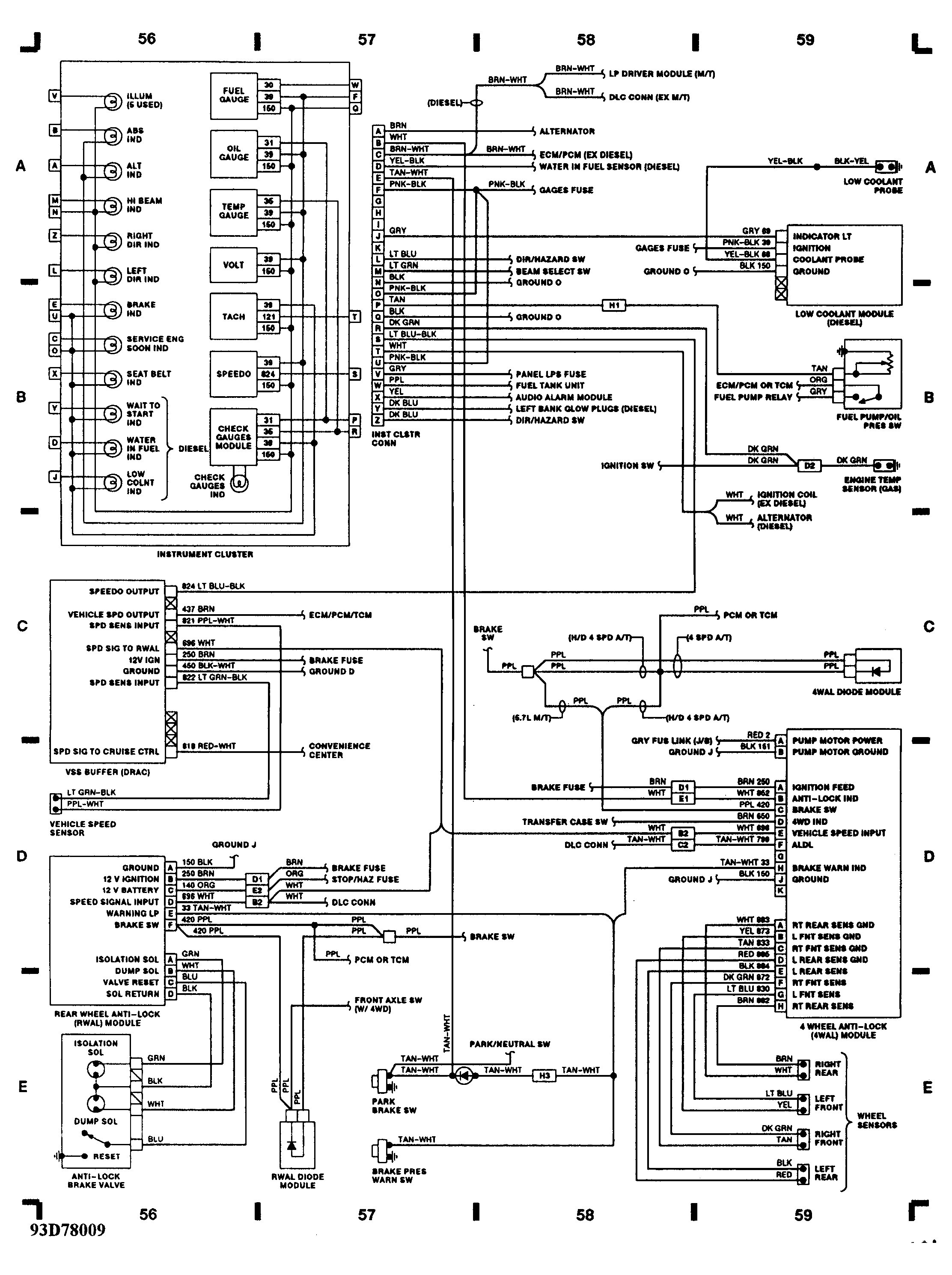
Searching for information regarding 1987 chevy truck wiring diagram for gas tanks. Posted on mar 25 2009.
 4 3 Chevy Tbi Ecm Wiring Diagram Wiring Diagram
 That eliminates the crankshaft and camshaft position sensors.

1987 chevy tbi wiring diagram. Generic tbi fuel injection block diagram acronyms individual components and their function. Need a 1988 454 chevy firing order wiring diagram. Wiring diagram for 1987 v20 chevy.
Placement of the sensors will determine wire length. Same design tbitpi except how esc is handled later on. Browse categories answer questions.
15112018 15112018 2 comments on 1987 chevy s10 28 tbi wiring diagram. 454 cid tbi chevrolet v20 question. In this episode we start to finish up the tpi to tbi conversion.
1987 chevy s10 25l tbi will not start. 1 8 4 3 6 5 7 2 number 1 should point toward number one cylinder and then go clockwise around the cap. Chevrolet v20 car and truck.
C then we will look at a couple schematics that show you pin connections for each component and normal gm wiring color codes. Tbi wiring harness conversion. Have you checked the fuel injector itself for an open winding or stuck valve plunger.
Or you are a pupil or maybe even you who just wish to know about 1987 chevy truck wiring diagram for gas tanks. Wiring diagram for 1987 chevy silverado 10 free downloands. There should not be a steady 12 volts to the injector if good injector it.
Gm throttle body injection 1987 93 lo3 50l and lo5 57l engines. S tbi no fuel spray from injector answered by a verified gm mechanic. This page is dedicated to the owners of these vehicles equipped with gms dual point fuel injection model 220 tbi.
Wiring diagrams r v p truck models when reference is made in this manual to a brand name number or specific tool an equivalent product may be used in place of the recommended item all information illustrations and specifications contained in this manual are based on the latest product. All thing wiring fuel lines and vacuum lines. We are not.
1987 chevy s10 28 tbi wiring diagram. Mike goes on a few rants of the dos and donts of how to wire correctly. Once you have each wire identified and layed out then you can set it up on the engine and start tailoring it to fit your engine.
You are right here. I could be totally wrong though id like to understand that diagram. You could be a professional who intends to seek references or solve existing problems.
System their wiring connections and a possible source or two with part numbers. Im looking at the wiring diagram and there is no hall effect on it. Looks to me like ppl.
Most stock harnesses are plenty long and only need to be shortened or wrapped and bundled. Internal to the ecm im at least partially wrong ecm pinout shows that white and ppl based on pin s above posted wiring diagram page white dont receive voltage unless the engine is running.
 Tbi Distributor Wiring Diagrams A Day With Wiring Diagram
  Chevy Tbi Wiring Harness Daily Update Wiring Diagram
  1987 Chevy 350 Engine Diagram Wiring Schematic Diagram
  87 Tbi Wiring Diagram Wiring Diagram
  A7ab 1987 Chevy Tbi Wiring Harness Epanel Digital Books
  Tag Archived Of 1987 Chevy Truck Wiring Diagram 1987 Chevy
  Chevelle Wire Harness Kit Wiring Diagram
  D15b435 1987 Chevy Tbi Wiring Harness Epanel Digital Books
  8f220 87 Gmc Tbi Wiring Diagram Digital Resources