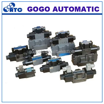
Here are some details of hydraulic pump electric diagram12vdc hydraulic power unit and 24vdc hydraulic power pack hydraulic circuit diagram and electrical diagram. Installation wiring practices for vickers electronic products.
 Wrg 8538 Gas Solenoid Valve Wiring Diagram
 Unsubscribe from ben hill.

Hydraulic solenoid valve wiring diagram. A wiring diagram is a simplified standard pictorial representation of an electric circuit. Collection of hydraulic solenoid valve wiring diagram. Designed to be used in conjunction with the appropriate vickers hydraulic valves.
Click on the image to enlarge and then save it to your computer by right clicking on the image. Connection not polarity. A wiring diagram is a simplified traditional pictorial depiction of an electrical circuit.
It shows the elements of the circuit as simplified forms and the power and also signal connections in between the tools. Valve solenoid connections note. Hydraulic solenoid valve wiring diagram lovely wanderleads cc gas solenoid valve wiring diagram best solenoid symbol diagram whats wiring diagram.
Wiring representations are made up of 2 things. Hydraulic solenoid valve wiring diagram gas solenoid valve wiring diagram best solenoid symbol diagram wiring diagrams schematics for hydraulic. How to wire dc hydraulic power pack unit.
Solenoid wiring instructions ben hill. A recent addition to the relevant global standards is the european electromagnetic compatibility directive emc 89336eec amended by. It reveals the components of the circuit as streamlined shapes as well as the power and also signal links in between the gadgets.
Collection of hydraulic solenoid valve wiring diagram. And more a wireless remote connect wire drawing also show below for single acting hydraulic power packthis wireless remote can be with a quick connector can be changed with our standard. I ordered recently a 12v dc solenoid valve a valve thats electrically controlled the datasheet of the valve is attachedhowever i received the valve without wires and im not sure about the wiring connection because there are three pins in the valve and i just want two wires out of the valve to connect it to a 12v dc battery.
Assortment of hydraulic solenoid valve wiring diagram. A wiring diagram is a type of schematic which uses abstract pictorial icons to reveal all the affiliations of elements in a system. Auto feed plus basic solenoid hydraulic valve test for wood chipper or stump grinder duration.
 Hydraulic Directional Control Valve Types Solenoid Wiring Polarity
  4 Way 3 Position Solenoid Valve Nfpa D03 Cetop3 Valve
  Hydraulic Pump Schematic Wiring Diagram Table
  Top 10 Punto Medio Noticias Hydraulic Schematic Symbols Solenoid Valve
  Hydraulic Solenoid Valve Wiring Diagram List Of Schematic Circuit
  Wiring Diagram Instructions For Hydraulic Diverter Machine Repair
  Hydraulic Solenoid Valve Wiring Diagram Cute Custom Hydraulic
  Hydraulic Solenoid Wiring Diagram
  Kualitas Tinggi Produsen Ningbo Hidrolik Solenoid Valve Pneumatic Dbe Wiring Diagram Buy Pneumatic Valve Diagram Solenoid Valve Hidrolik Wiring